
Engineering Records · Wildlife Detection Platform
Scout Alpha 1 Mechanical Baseline
Establishing the first reviewed mechanical reference for the Scout Alpha 1 enclosure using the purchased hardware, confirmed measurements, provisional dimensions, and enclosure architecture that will guide future CAD revisions.
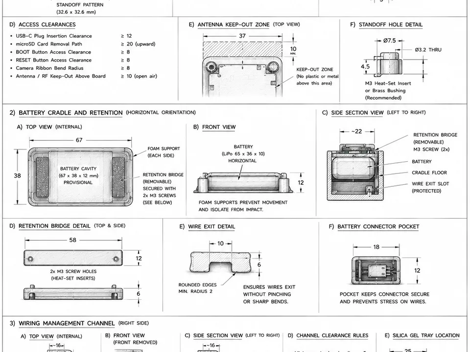
Scout Alpha 1 — Board, Battery, and Wiring Supports
Concept designReviewed A0.2 concept sheet documenting the controller-board mounting, safe LiPo retention, and internal wiring-support strategy for Scout Alpha 1.
The Scout Alpha 1 enclosure is the first purpose-built housing for the battery-powered detection node within the Wildlife Monitoring Platform.
This document establishes the initial mechanical design specification before detailed CAD modeling begins. It defines the selected hardware, enclosure architecture, component layout, and packaging constraints that will guide development through the first generation of prototypes.
Rather than attempting to optimize every dimension from the beginning, this specification focuses on creating a practical, serviceable enclosure that provides a solid foundation for future revisions as real-world testing begins.
This document should be treated as the initial mechanical specification for Scout Alpha 1. Dimensions and layouts will continue to be refined as purchased components are measured, prototypes are assembled, and testing identifies opportunities for improvement.
Design Objectives
Scout Alpha 1 is intended to become a compact, battery-powered wildlife detection node that can operate independently or as part of a larger system.
The enclosure should:
- Protect electronics from dust, rain, and normal outdoor exposure.
- Keep the camera’s optical path unobstructed.
- Expose the PIR sensor directly to the environment.
- Secure the battery safely without compressing the pouch.
- Allow straightforward assembly and servicing.
- Provide access to development interfaces during prototyping.
- Support repeatable tree or post mounting.
- Print reliably in PETG on a Bambu Lab A1 Mini.
- Leave room for future hardware improvements without redesigning the overall architecture.
The first enclosure prioritizes reliability, accessibility, and ease of iteration over achieving the smallest possible size.
Selected Hardware
| Component | Selected Hardware |
|---|---|
| Controller | Waveshare ESP32-S3 AIoT Camera Board |
| Camera | OV5640 |
| Motion Sensor | SR602 Mini PIR |
| Battery | 3.7 V 3000 mAh LiPo |
| Storage | Integrated microSD |
| Enclosure Material | PETG |
| Rear Seal | 2 mm Silicone Gasket |
| Fasteners | M3 Stainless Steel Screws |
These components establish the physical constraints that the enclosure is designed around.
Controller Board
The main controller is the Waveshare ESP32-S3 AIoT Camera Development Board.
Confirmed PCB Dimensions
| Feature | Dimension |
|---|---|
| PCB Width | 37.0 mm |
| PCB Height | 37.0 mm |
| Horizontal Hole Spacing | 32.6 mm |
| Vertical Hole Spacing | 32.6 mm |
| Mounting Holes | 4 |
| Hole Diameter | Approximately 4.5 mm |
Reserved CAD Envelope
- PCB: 37 × 37 × 10 mm
- Board and camera assembly: 37 × 37 × 20 mm
- Camera clearance envelope: 22 × 22 × 12 mm
The enclosure must also provide access to:
- USB-C connector
- microSD slot
- Power and Boot buttons
- Camera ribbon cable
- Onboard antenna clearance
Camera Module
Scout uses an OV5640 camera module.
Optical Specifications
| Feature | Value |
|---|---|
| Resolution | 2592 × 1944 |
| Sensor Format | 1/4" |
| Focal Length | 4.1 mm |
| Aperture | f/2.8 |
| Horizontal FOV | Approximately 55° |
| Vertical FOV | Approximately 42° |
| Diagonal FOV | Approximately 68° |
The enclosure uses a replaceable clear polycarbonate window.
Current design target:
- Window: 26 × 26 × 2 mm
- Clear aperture: approximately 18 × 18 mm
- Replaceable retaining frame
- Matte black internal light path
- Small air gap between lens and window
The lens should never contact the protective window.
Motion Sensor
Scout uses an SR602 Mini PIR sensor for motion detection.
Design Envelope
- Body diameter: 15–16 mm
- Fresnel dome: 10–11 mm
- Installed depth: 20–25 mm
- Front opening: 11–12 mm
- Retaining recess: 15–17 mm
The sensor board remains inside the enclosure while the Fresnel dome passes through its own sealed opening.
A small integrated rain hood is planned to reduce direct weather exposure.
Battery
Scout uses a 3.7 V 3000 mAh lithium-polymer battery.
Battery Dimensions
- Length: 65 mm
- Width: 36 mm
- Thickness: 10 mm
- Weight: approximately 49 g
Battery Compartment
- Cavity: 67 × 38 × 12 mm
- Wire exit: 15 × 12 × 8 mm
- Connector pocket: 12 × 8 × 5 mm
The battery will be supported with thin foam and retained using a removable bracket or hook-and-loop strap.
No screws or printed features should create pressure points against the battery.
Connector pitch alone does not guarantee compatibility. Battery connector type and polarity should always be confirmed before connecting power.
Enclosure Dimensions
The initial enclosure is based on the following starting dimensions.
| Feature | Dimension |
|---|---|
| External Height | 100 mm |
| External Width | 70 mm |
| Body Depth | Approximately 46 mm |
| Total Depth with Hood | Approximately 60–63 mm |
| Wall Thickness | 3 mm |
| Front Wall | 3–4 mm |
| Corner Radius | 6–8 mm |
| Rear Flange | 7–8 mm |
Estimated usable internal space:
- Height: 92–94 mm
- Width: 62–64 mm
- Depth: 35–39 mm
Component Layout
The current layout places components as follows:
- Camera centered near the top front.
- Controller board mounted directly behind the camera.
- PIR sensor positioned on the right service centerline.
- Status LED aligned with the PIR.
- Power switch mounted on the left side.
- Wiring routed primarily along the right side.
- Battery mounted horizontally in the lower section.
- Four integrated PCB standoffs.
- No bottom cable gland.
This arrangement simplifies wiring, protects the battery, and keeps the camera centered within the enclosure.
Internal Assembly
The enclosure is organized from front to back as follows:
- Front enclosure wall
- Camera and PIR mounting features
- Camera and controller assembly
- PCB standoffs
- Battery
- Foam support
- Rear clearance
- Rear gasket and service lid
The controller and battery may overlap in depth but should never contact one another.
PCB Mounting
The controller mounts using four integrated printed standoffs.
Starting Geometry
- Outside diameter: 7–8 mm
- Height: 4–6 mm
- Fastener: M3
Because the PCB mounting holes are larger than the screw diameter, the design should prevent lateral movement without stressing the board.
Rear Service Lid
The rear lid provides access for assembly and maintenance.
Starting Design
- Lid thickness: 4 mm
- Rain skirt: 6 mm
- Locating lip: 4 mm
- Sliding clearance: approximately 0.3–0.4 mm per side
Gasket
- 2 mm silicone
- 5–6 mm wide
- Continuous rectangular loop
Rear screws remain outside the sealed electronics compartment.
Camera Hood
The camera hood is designed as a separate replaceable component.
Starting dimensions:
- Width: 36–42 mm
- Projection: approximately 15 mm
- Thickness: 2.5–3 mm
- Side walls: 8–12 mm
- Downward angle: 5–10°
Its purpose is to:
- Reduce rain on the camera window
- Shade the lens
- Improve image quality
- Provide a controlled drip edge
Switch and Status LED
Current design envelopes:
Power Switch
- Opening: 13 × 6 mm
- Body: 18 × 8 × 8 mm
- Rear clearance: 12–15 mm
Status LED
- 3 mm indicator
- Sealed using a dedicated light pipe or transparent plug
Tree Mount
The mounting system remains separate from the rear service lid.
Backplate
| Feature | Dimension |
|---|---|
| Height | 86–92 mm |
| Width | 58–62 mm |
| Thickness | 4 mm |
The mount uses:
- Two 25 mm straps
- Printed guide rails
- Sliding attachment channels
- One lower retaining screw
- Rubber contact pads
- Drainage gap behind the enclosure
Separating the mounting system from the rear lid allows the enclosure to be serviced without removing it from the tree.
Measurements Still Required
Before detailed CAD can be finalized, the following measurements should be verified using the purchased hardware.
Controller
- PCB thickness
- Component height
- Camera carrier dimensions
- Lens diameter
- Lens protrusion
- Ribbon bend radius
- USB-C position
- microSD access
- Battery connector location
- Mounting hole diameter
PIR Sensor
- PCB diameter
- Dome diameter
- Dome height
- Installed height
- Pin spacing
Battery
- Actual dimensions
- Protection board thickness
- Wire exit
- Connector dimensions
- Connector polarity
Switch and LED
- Final body dimensions
- Mounting geometry
- Terminal clearance
Prototype Validation
Before moving beyond the initial enclosure design, the following should be completed:
- Measure every purchased component.
- Print calibration blocks for threaded inserts and pilot holes.
- Validate PCB mounting.
- Verify camera window clearance.
- Test PIR fit.
- Test gasket compression.
- Verify sliding mount tolerances.
- Assemble the first complete enclosure prototype.
Conclusion
This specification establishes the initial mechanical design for Scout Alpha 1 and provides the foundation for future enclosure development.
As prototype work progresses, measurements will become more accurate, clearances will be refined, and individual features will continue to evolve. The overall architecture, however, is intended to remain consistent throughout the Alpha 1 design process so improvements can be made without repeatedly redesigning the enclosure from scratch.
Supporting Media
Prototype photographs
Scout Alpha 1 — Main Enclosure Body
Reviewed A0.2 concept sheet defining the starting enclosure body geometry, wall structure, and service volume for Scout Alpha 1.
Concept designScout Alpha 1 — Rear Lid and Weather Seal
Reviewed A0.2 concept sheet documenting the rear service lid, continuous gasket loop, and weather-sealing strategy for Scout Alpha 1.
Concept designScout Alpha 1 — Camera Optical Assembly
Reviewed A0.2 optical-assembly concept for the Scout Alpha 1 camera window and replaceable rain hood. Final aperture and hood dimensions must be validated against the real camera field of view.
Concept designScout Alpha 1 — PIR, LED, and Power Interfaces
Reviewed A0.2 concept sheet documenting the PIR, status LED, and power-switch interfaces. Final openings and recesses remain subject to physical measurement.
Concept designSupporting media
Scout Alpha 1 — Exterior Dimensional Baseline
Reviewed A0.2 concept sheet establishing the starting exterior dimensions and mechanical proportions for the Scout Alpha 1 enclosure. Dimensions remain provisional until the purchased hardware is verified with calipers.
Concept designScout Alpha 1 — Canonical Internal Packaging
Reviewed A0.2 concept sheet documenting the canonical internal packaging for Scout Alpha 1. Component interfaces and dimensions remain provisional until the purchased hardware is verified with calipers.
Concept design